
Radar
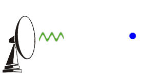
Radar transmitters send out short powerful microwave pulses between 1 and 20 cm in wave length. A portion of the energy is reflected back from objects towards the transmitter and is captured by a receiver, where it is stored and displayed on a monitor as an echo. The difference between the transmission and receive time is used to calculate distance from target. The wavelength of the received energy is used as a measure of precipitation droplet size. The brightness, or amount of energy received, can be used to measure intensity. Radar is an active sensor, in that it transmits an EM signal to illuminate a target and records the response returned from the target. The benefit of an active sensor is that it can operate anytime, without a requirement such as sunlight.
Imaging radars operate on various wavelengths throughout the EM spectrum. For real aperture radars (RAR), resolution as wavelength decreases. [ use fig ] These are the oldest and simplest radar systems. The transmitter sends a signal of a certain wavelength at the ground using an antenna, and the reflected signal is then received by the antenna and is amplified and filtered. The data is then displayed on a cathode ray tube (CRT) and is recorded on film, or newer electronic equipment. The size of the illuminated area is dependant on many variables, including antenna size versus wavelength. To achieve fine detail, a long antenna is required, which is often the limiting factor to resolution. Synthetic Aperture Radars (SARs) utilize the movement of an antenna, to create a longer, synthetic, antenna, to increase resolution.
(http://weather.noaa.gov/radar/radinfo/radinfo.html, April 5th, 2002)
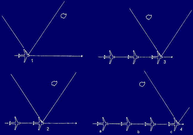
Synthetic aperture imaging radar accumulates a history of signals from the landscape as the antenna moves along path abc, synthetically creating an antenna from a to c. (Campbell, 1996)
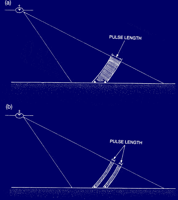
The effect of pulse length on the differentiation of objects. The shorter the pulse length, the greater the resolution of the data. (Campbell, 1996)
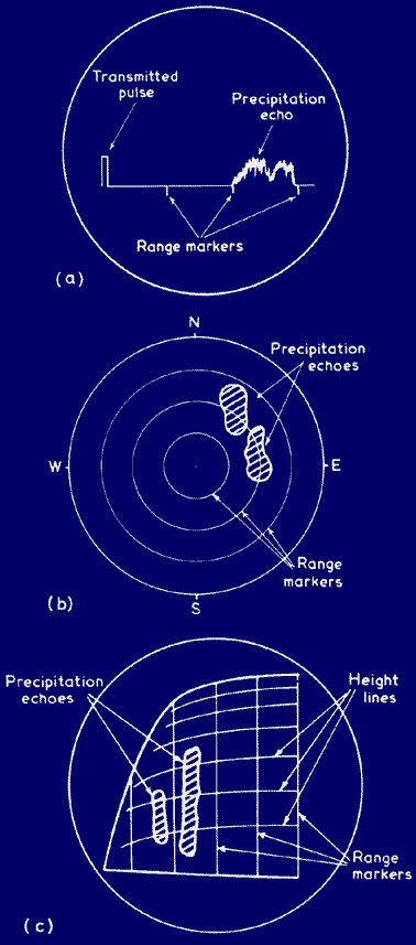
Radar Displays (Barrett et al., 1999)
(a) The A-scope presents a profile of back-scattered energy by and allows for the examination of echo intensities.
(b) The plan position indicator (PPI) gives a horizontal view and can be used to identify rainfall areas, and determine distrution and types of rainfall. Using intensity modulation, bright spots are displayed which correspond to the intensity of the reflected radar beams. (c) The range height indicator displays a vertical profile of the atmosphere when recieved from vertically scanning radar. This indicator also uses intensity modulation.
Doppler Radar
Doppler radar uses the principle of Doppler shift to measure the speed of the precipitation moving horizontally towards or away from the station. This allows for an estimate of wind speed. With the recorded Doppler shift, computer algorithms can estimate total rainfall.
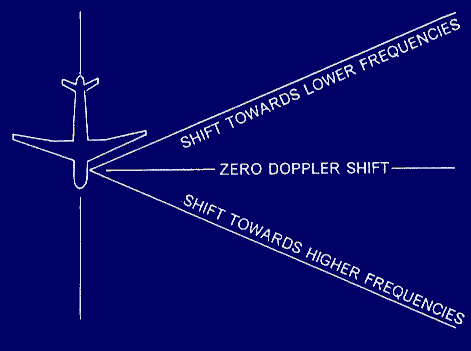
Within the field of view of the radar system, frequency shifts exist. (Campbell, 1996)
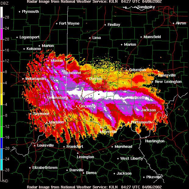
Doppler Radar Image of Weather Pattern Over Cincinnati (http://weather.noaa.gov/radar/latest/DS.p19r0/si.kiln.shtml, April 5th, 2002)
Lidar
Lidar (Light Detection and Ranging) uses infrared and visible light in the form of a laser beam to measure wind velocity by measuring the movement of particles that reflect the laser beam.